Passive Harmonic Filter
Passive Harmonic Filter
Most of the known filtering techniques have common draw- back of higher cost compared to broad band filtering techniques. Consequently, the harmonic filtering techniques to a large extent are still the most commonly used techniques forcurrent harmonics mitigation of 6-pulse front-end diode rectifier application.
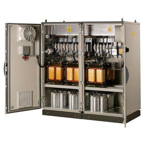
Here in ACE we have developed an efficient broad band filter, which can suit many such similar loads. Since all filter components are passive they are rugged,maintenance free, reliable and low cost. Moreover, the filter implementation procedure is relatively easy.
With simple structure, our broad band filters have been extensively used for VFD harmonic mitigation. No involvement of electronic circuits, hardware’s and complicated control algorithms. Hence, our Broad Band harmonic filters are relatively inexpensive means for eliminating current harmonics distortion & improving the system power factor. Because of these two in one features our broad band filters usually have edge over the other effective filtering methods.
There are various techniques of filtering. Most prominent is Shunt Passive Filters, hich are tuned to the desired frequencies. These methods are workable to certain extent with non satisfactory results in harmonic mitigation. Lots of Shunt connected filters tend to resonate with the transformer impedance and also stray harmonics.
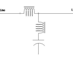
ACE Broad Band Filtering has a Series Low Pass and Shut High Pass Filter which in fact acts as a source to Load harmonic demand. This effectively reduces the harmonics at the main source end. This in turn allows us to install the Filters near the load, Directly reducing the I2R losses and skin effect of the bus ducts. The 3P3W system requires balance load and the 3P4W system can correct unbalance upto 25%.

Typical Application Areas
Front end Six-pulse DC
rectifiers
Automation equipment’s
Waste water/effluent
treatment Plants
HVAC Equipment’s using Motor
Drives VFD’s and Motor applications
Battery Chargers
Electrical Schematic

Technical Specification
| Sample ID | Heading 1 | |
|---|---|---|
| Sample #1 | Row 1, Content 1 | Row 1, Content 2 |
| Sample #2 | Row 2, Content 1 | Row 2, Content 2 |
| Sample #3 | Row 3, Content 1 | Row 3, Content 2 |
Features and Benefits
- Helps meet IEEE-519 Requirements.
- Guarantees THDi performance of 8% Max at 50% load, 5% MAX at full load.
- Meets the voltage and current distortion limits of IEEE-519.
- Saves energy by eliminating the wasted energy associated with harmonics, therefore reducing the true RMS KVA demanded from your power source.
- Suitable for Speed Controllers or Inverters
- Reduces energy costs.
- Increases equipment reliability by absorbing transients and voltage surges.
- Increases equipment life by reducing heat associated with harmonic currents
- Improves Power Factor.
- Reduces THDv to meet Power Quality Standards.
- Uses fewer capacitors while maintaining more than 97% efficiency
- More consistent power factor across the load range.
- Improves C/L ratio, which decreases potential resonance
- Lowers capacitance resulting in less voltage rise at no load, at PCC (Point of Common Coupling) and on the DC Bus.
- Inductor Addition at the Input of the ACE BBF available at load less than 20%. To maintain Power Factor.
